
Vision-Guided Pick and Place Robots for Manufacturing
Vision-guided pick and place locates each part with a camera before the robot moves, so parts on conveyors or trays no longer need precise fixtures. It handles changes in position, orientation and format without re-tooling the station.
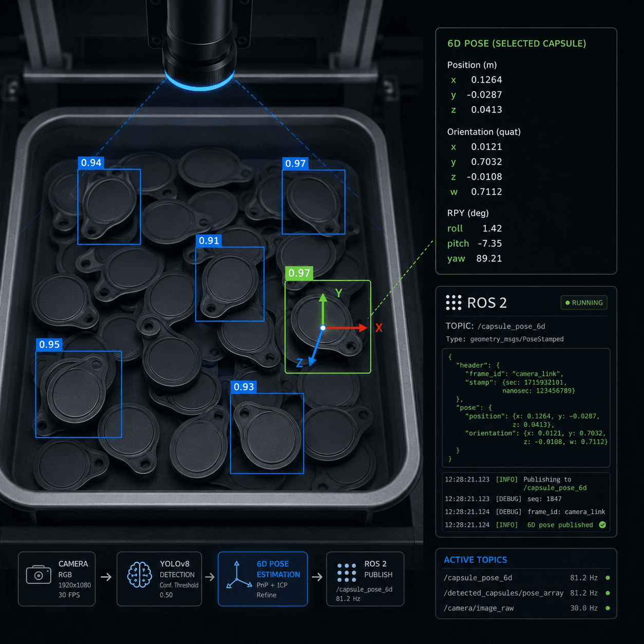
What the task looks like on the shop floor
Classic pick and place assumes the part is always at the same position and orientation. That assumption holds with precise fixtures, indexed pallets or a well-tuned feeder. It breaks as soon as parts arrive loose on a conveyor, sit anywhere in a tray, tilt against each other or change format from one batch to the next.
The usual answer is mechanical: guides, stoppers, nests and format parts for every product variant. Each variant adds tooling, changeover time and a new source of jams. When the product mix grows, the station spends more time being adjusted than running.
Typical situations
- Parts on a moving conveyor without a fixed pitch or orientation
- Trays or blisters with loose parts that shift during transport
- Format changes that require nests, guides or stoppers to be swapped
- Stacked or tilted parts that a 2D camera cannot locate reliably
- Operators correcting mis-picks or re-orienting parts by hand
- New product variants that force a mechanical redesign of the station
When a robotic application makes sense — and when it does not
An honest fit check is the first thing we do. Not every task needs a robot, and not every robot task needs vision.
It usually makes sense when
- Parts arrive on conveyors or in trays without a precise, repeatable position
- The station handles several formats and changeover should not require re-tooling
- Flat parts on a plane can be located with 2D vision and a calibrated camera
- Stacked, tilted or overlapping parts justify a 3D camera and pose estimation
- Parts must be picked from a moving conveyor with tracking instead of stop-and-go
- Placement into the downstream machine or package needs orientation correction
It usually does not make sense (yet) when
- Parts always arrive in the same position and a fixed fixture already places them repeatably
- One stable product, no format changes, and a mechanical feeder or indexer does the job
- Cycle time leaves no margin for image acquisition and processing, and no buffer is possible
- Parts are transparent, highly reflective or indistinguishable from the background under any practical lighting
- Placement tolerances are tighter than what camera calibration and robot repeatability can deliver together
What we typically use
- Industrial robots
Sized for reach, payload and cycle time; SCARA or delta kinematics when the task is planar and fast
- 2D/3D vision systems
Calibrated 2D cameras for flat parts on a plane; 3D cameras for stacked, tilted or overlapping parts
- Conveyor tracking
Encoder-synchronized picking from a moving belt without stopping the line
- Format recipes
Part parameters stored in the vision and robot software so changeover is a recipe switch, not a re-tooling
- Digital twin validation
Reach, cycle and tracking checks in simulation tools such as NVIDIA Isaac Sim before hardware is ordered
- PLC / robot integration
Handshake with the conveyor, upstream machine and downstream packaging, with clear fault states
From task to validated robotic application
We start from the production task, not from the robot. Each step reduces technical risk before the next investment.
- Step 01
Assessment on your line
We start from how parts actually arrive: conveyor speed, tray layout, part variants, the placement target and what happens on a mis-pick.
- Step 02
Vision feasibility
We test detection on samples of your parts under realistic lighting and decide between 2D and 3D vision. Deterministic detection comes first; Physical AI is used only when deterministic automation is not flexible enough for the part mix.
- Step 03
Digital twin and pilot
We validate reach, cycle time and conveyor tracking in simulation, then build a pilot cell with the real camera, gripper and parts.
- Step 04
Integration and deployment
We integrate the application with the PLC-controlled line and its format recipes, together with mechanical, electrical and safety partners when needed.
Related services: Robot Application Assessment, Digital Twin Validation, Robotic Pilot Cell, PLC / Robot Integration.
Often combined with
- Bin PickingVision-guided picking of randomly oriented parts from bins, trays or containers.
- Packaging HandlingRobotic handling of packaging components, containers, bottles, lids, trays, cartons and end-of-line products.
- SortingRobotic or vision-guided sorting of parts, products or packaging formats.
- PLC / Robot IntegrationPLC-connected robot applications, machine handshake, safety states, I/O mapping and industrial software integration.
Parts that never arrive in quite the same place?
Send a photo or short video of how the parts arrive on the conveyor or in the tray. We can tell you whether 2D or 3D vision-guided pick and place is realistic and what the first technical step would be.