
Digital Twin Validation for Robotic Cells
A digital twin is a simulated model of the robotic cell: robot, gripper, fixtures, conveyors, guards and the parts that move through it. It lets you check reach, layout, collisions, sequence and control logic before steel is cut or a robot is ordered.
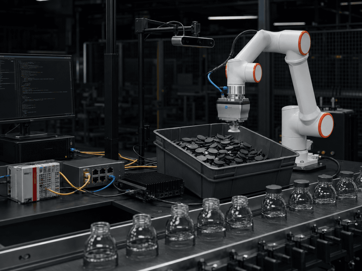
What the task looks like on the shop floor
Most robotic cell decisions are made early, on a 2D layout and a spreadsheet: which robot, where it stands, how far it reaches, how many parts per minute it will handle. If one of those assumptions is wrong, it is usually discovered at commissioning, when the mechanics are built, the cabinet is wired and the schedule has no margin left. Fixing it then means a bigger robot, a moved conveyor or a redesigned gripper.
A digital twin moves that discovery forward. Robot kinematics, cell geometry and process sequence are modelled together, so reach limits, singularities, collisions with guards or fixtures, and unrealistic cycle assumptions show up while they are still cheap to correct. The same model can run the PLC sequence and the robot program against a virtual cell, so handshake logic, interlocks and error branches are exercised before the first I/O is wired.
Typical situations
- Robot selection based on reach and payload tables, not on the real gripper and part path
- Cell layout fixed in CAD before anyone has checked joint limits and approach angles
- Cycle time promised from a rough sum of moves, with no motion-level verification
- PLC and robot sequence written separately and first tested together on the machine
- Layout changes late in the project because of a collision or an unreachable pick position
- Several concept variants on the table, with no objective way to compare them
When a robotic application makes sense — and when it does not
An honest fit check is the first thing we do. Not every task needs a robot, and not every robot task needs vision.
It usually makes sense when
- A new robotic cell or line section is being designed and the robot, layout or gripper is not yet fixed
- Reach, approach angles or collisions are uncertain because of tight spaces, guards or existing equipment
- Cycle time is a commitment and the motion sequence needs verification before it is promised
- PLC logic, robot program and safety states must be tested together before commissioning on site
- Several concept variants (robot size, position, tooling) must be compared on the same basis
- A machine builder or system integrator wants a validated concept to support a proposal or a design review
It usually does not make sense (yet) when
- The cell is a simple repeat of a layout that already runs and nothing in the geometry or cycle has changed
- The main unknown is gripping reliability, part variation or vision robustness — these need hardware tests on real parts, not a simulation
- No usable CAD of the parts, tooling and cell environment exists and cannot be produced at reasonable effort
- The project timeline or budget does not allow the model to be kept aligned with design changes
- The result is required to be an exact cycle time to the tenth of a second; simulation gives a validated estimate, not a measured one
What we typically use
- Robot kinematic models
Manufacturer-accurate 6-axis robot models with joint limits, reach envelopes and singularity checks
- Cell layout from CAD
Fixtures, conveyors, guards, cabinets and parts imported from your CAD to check clearances and collisions
- Physics-based simulation
Simulation tools such as NVIDIA Isaac Sim for motion, collision and sequence checks on the full cell
- Motion planning and cycle analysis
Reachability, approach and retract paths, and motion-level cycle estimates per part flow
- Virtual commissioning
PLC program and robot sequence run against the virtual cell to test handshake, interlocks and error branches
- Vision system placement
Camera position, field of view and occlusion checks — vision robustness itself is validated on hardware
From task to validated robotic application
We start from the production task, not from the robot. Each step reduces technical risk before the next investment.
- Step 01
Define what must be validated
We start from your layout, parts, cycle target and open questions: which robot, where it stands, what it must reach, what the PLC must control. The model is only as detailed as those questions need.
- Step 02
Build the digital twin
We model the cell from your CAD with the candidate robot, gripper, fixtures and conveyors, and define the part flow and process sequence as the real cell would run them.
- Step 03
Validate and compare
We check reach, joint limits, collisions and cycle assumptions, run the PLC and robot logic against the virtual cell, and compare variants. You get a written report with what passed, what failed and what changed.
- Step 04
Hand over to hardware
What simulation cannot answer — gripping physics, vision robustness, real cycle under production conditions — goes to a robotic pilot cell or bench test with the real parts. The validated model then supports integration and later changes.
Related services: Robot Application Assessment, Digital Twin Validation, Robotic Pilot Cell, PLC / Robot Integration.
Often combined with
- Robotic Pilot CellsSmall-scale robotic pilots to validate a task before investing in a full production cell.
- PLC / Robot IntegrationPLC-connected robot applications, machine handshake, safety states, I/O mapping and industrial software integration.
- Machine TendingRobotic loading and unloading of machines, fixtures, trays, stations and process equipment.
- Bin PickingVision-guided picking of randomly oriented parts from bins, trays or containers.
Designing a robotic cell and not sure it will reach, fit or make cycle?
Send us the layout, the parts and the cycle target. We can tell you which assumptions a digital twin can validate, which ones need hardware tests, and what the first step would be.